


|
|
Scratchbuilding the C&O’s
Louisa Freight House
The C&O built an 1892 standard design passenger station in Louisa in 1899. At the same time, I suspect, they built the freight station that is the subject of this project. The freight station stands about 18' to the east of the passenger station. I don’t believe it was built to a standard design. In fact, there’s little that’s standard about it.
 |
| Figure 1. This is the freight station we’re building. It’s relatively unremarkable, but it does have a few unique features. I especially like the round windows in the ends. (1998 photo) |
Perhaps I should explain that last remark. I discovered in the course of this project that lumber sizes were not standardized in the US until the 1920’s. That fact wrought havoc on my first attempts to plan my model; I was trying to use what I know about lumber sizes to take measurements from my photos. And I couldn’t get it to work. In frustration I took my tape measure and drove the 3½ hours to Louisa to measure the thing.
 |
| Figure 2. This 1973 shot gives a nice view of the station in its better days. The freight house, the passenger station, and the little shed across the tracks from them make an attractive scene for modelers. (LaVerne Brummel photo, used with permission) |
What I found when I measured the station surprised me. The battens, for instance, are made of 1x3’s that are actually 1" by 3"! And they're not spaced evenly, either, especially on the east end of the station. To see what I mean, take a look at Figure 3. I find, though, that that kind of detail simply adds to the charm of this structure. Overall, the station is 73'6" (70'6" on the ground with 18" of roof overhang at each end) and 21' deep. Great size for a model, eh? So, load up on strip styrene, especially .010x.040 and sheet styrene (.010, .020, and .040) and let’s get to work.
 |
| Figure 3. Here’s a good look at the round window in the east end of the station. Note the irregular spacing of the battens. (2002 photo) |
Planning is important for a project like this. I had plenty of photos of the station, but, as I mentioned above, creating scale plans from them was almost impossible. A trip to Louisa corrected that and I drew up a rough set of plans to work by. All I was aiming for in the plans was the overall dimensions of the building with major features roughed in so I could make sure I was on the right track. A link to those plans in PDF form follows.
![]() drawings.pdf
drawings.pdf
![]()
You must have the Adobe Acrobat reader installed to use this file. If
you do not have the Acrobat reader, you can get it by clicking the “Get Acrobat
Reader” icon above. To download the drawings, right click the link and select
“Save Target As” from the menu.
Please note that these are not meant to be detailed plans of the station. I laid out only the principle dimensions and noted those on the drawings. Also, the door and window measurements noted are the sizes to the outside of the frames. The drawings show the track side of the building and the east (window) end. The west end is identical to the east end, except the door extends down to the same point as the freight doors on the track side. I haven’t provided a plan for the land side of the station; on my layout it will never been seen, so I didn’t model it. A photo of the land side is shown below, should you want to model it on your layout.
A couple of the choices that I made for this model might seem odd. The choice to not detail the back wall might seem to be so, but I really don’t believe in modeling what cannot be seen (and this decision might make even more sense in light of the next point). I also chose to forego the use of commercial board and batten siding and make my own. This decision was motived by the desire to model the odd pieced-together look of the siding, especially the ends. I'm sure that a very nice model of this station could be built using commercial siding; if you choose to go that route adjust my instructions accordingly.
 |
| Figure 4. The land side of the station. It’s very similar to the track side, except for some modifications for handling trucks. (1998 photo) |
Track side Wall. Start by cutting the track side wall from .040" sheet styrene. The door openings should be a scale 85" wide, plus .010 on each side for the framing. They should be 96" high, plus .030 (.020 for the sill and .010 for the top of the frame). Mark the openings as accurately as possible, then cut inside the lines you made and use files and sandpaper to obtain the final size. Once you’ve cut out the doors, bevel the ends of the wall at 45 degrees (we’ll do the same on the ends to get a nice joint). Now let’s frame the doors. Refer to Figure 5 and cut two pieces of .010x.080 strip for the inner part of the uprights. Glue them in place extending through the side and out the back (these pieces give the frame its depth). The front of the piece should be flush with the front of the wall. Now cut the top piece of the frame from .010x.080 and drill a series of 9 holes using a #80 drill bit in a pin vise. See Figure 6. These holes will fall behind the wall. Finally, cut the door sill from .020x.010 strip. It should be wider than the door opening (with the upright pieces in place) by .120 (.060 on each side). Notch the sill to fit into the door opening, leaving a scale 3" extending beyond the front side of the wall. Now to the outside of the frame. Cut the two uprights from .010x.060 strip and glue them in place. Cut a top piece of .010x.060 and cement it in place. Let the frames dry before proceeding to the next step.
 |
| Figure 5. Details of the door framing. |
 |
| Figure 6. Top of a door frame. Note the evenly spaced row of 9 .012" holes. |
There is a 7" wide strip that runs the length of the side below the doors; make it from .010x.080 styrene strip. Go ahead and glue it in place, but use a straightedge and get it as straight as you possibly can. We’ll butt the bottom edge of the battens up against this strip, so it’s important to get it right. Next, cut a strip of .010x.125 to go along the top of the wall, but don’t glue it in place yet. Now for the fun. The battens are made from .010x.040 styrene strip. Cut them to fit between the strip below the doors and the strip at the top of the wall. I used a NWSL Chopper II to cut my battens to length. I think it took 50-60 to do the track side wall and it helped to cut them all at once. I used a spacer of .060x.060 styrene between most of the battens, but I did adjust the spacing to match odd spacings visible in photographs around the doors. Make sure to get the first batten strip on perfectly vertical. The spacer then helps keep the subsequent battens straight. I found that I could only glue down 5 to 10 battens at a time without my spacer getting sticky. See Figure 7 for a photo of the wall as I started. Once all the battens are in place, add the top strip. That completes the track side wall for now.
 |
| Figure 7. Here’s a shot of the track side wall with the first few battens in place. A pile of battens and the spacer are above the wall. Note that I started out with the wall too short; I hadn’t included the material below the 7" strip on the bottom. Good planning is essential, believe me. |
East Wall. This is where life got interesting. The battens are really unevenly spaced on this wall and that, combined with the slope for the roof, ensured that no two batten strips were the same. Start by cutting the wall from .040 styrene sheet. Bevel the track side edge to mate with the track side wall (I left the land side edge flat and just cut the land side wall to fit between the two ends). Cut out the window opening, again cutting inside your lines and using files and sandpaper to achieve the final size. Frame the window in the same manner as the freight doors. The strip along the bottom of the wall is 10"wide on the prototype; I cut a strip a scale 10" wide from .010 sheet styrene.
I worried for a long time about how to build the round windows in the ends of this station. Then I noticed that, by 1970 (my modeling period), the glass had been painted white. Not having to include clear “glass” simplified construction. I started with Evergreen 7/16" tubing. The inside diameter is just right for the inside diameter of the frame for the window. I needed to cement a strip of .010 styrene around the outside of the tubing to bring the width up to the width of the prototype frame. Now, cut a slice of the tube off as close to .010 thick as you can get. I cut a little oversize and then sanded down to the final thickness. Glue this piece in place on the wall. Now, cut a thin slice of a piece of Evergreen 1/16" rod and glue it in the exact center of the window. Make the 8 radius pieces from .010x.020 strip. Note that the window is not set up with one set of radius pieces going straight up and down. See Figures 3 and 8 to see what I mean.
 |
| Figure 8. This is the east end of the station with all of the detail in place. Note especially the construction of the round window. |
Ok, now add the strips along the top edge. They're made from .020x.100 strip. Note that I cut mine too long and cut them back to the proper length later. You can now begin cutting the batten strips. If you look carefully at Figure 9 you can make out the odd spacing of the battens in order to duplicate it on your model.
 |
| Figure 9. This is the east end of the prototype station. The day was cloudy, so the picture is a little dark, but careful examination will show the spacing of the battens and the details of the windows. |
The window in this end has 15 small panes. I built up the window in place using .010x.020 strip. When you’ve completed that, this end is done for now. There are bars over the window, but we’ll add those later, after the window is glazed.
 |
| Figure 10. Here are the details on building the door in the west end of the station. |
West Wall. Construction of the west end of the station is similar to that of the east end. The only real difference is that you’ll be building a door rather than a window. I’ve never seen the door in the prototype station; every time I’ve been there the door has been open and in the shadows inside the station. I based my door on the doors included in the Gloor Craft Marlinton station kit (which I’ll be using to model Louisa’s passenger station. See Figure 10 for details of the door. I glued a scrap piece of sheet styrene behind the door opening and built the door in place using the sizes of strip styrene listed in Figure 10. A prototype photo of the west end is shown in Figure 11 and the completed west end of the model is shown in Figure 12.
 |
| Figure 11. Here are the details on the west end of the prototype station. |
 |
| Figure 12. Here’s the completed west end of the model station. |
Land Side Wall. There’s not much to this on my model. It’s pretty much just a blank piece of .040 sheet styrene. I did wrap a little detail around so that it would look like there was something there should someone get an end-on view, but that’s as far as I went.
Building the Freight Doors. Our next step is to build the freight doors for the track side wall. These are big, sliding doors with transom windows. At some point before 1970 the railroad installed security bars over the transom windows. A detail view of the bars is shown in Figure 13.
 |
| Figure 13. These security bars and the diagonal boards in the doors make interesting details that set this station apart from similar buildings. |
To make the doors, refer to Figures 14 and 15 and use Evergreen’s passenger car siding with 3¼ spacing. The doors are 6'6" high and wide enough to extend beyond the door frame. Cut the doors so that the scribing is on a 45 degree angle, sloping upward to the right. Glue these in place in the door openings. Now cut and add the vertical pieces on each side of the door; these are made of .010x.060 strip. Now cut and attach the three horizontal pieces. From top to bottom these are made from .010x.040, .010x.080, and .010x10 scale inches. The transom windows had also been painted over by 1970, so I started them by cutting a piece of scrap styrene sheet to cover the transom area. Glue it in place and build up the transom framing with .010x.020 strip. Each transom has 8 equally-sized panes.
 |
| Figure 14. Here are the details of the construction of the freight doors. |
 |
| Figure 15. Here’s a completed door. I haven’t yet gotten a photo that clearly shows the transom detail. |
Now for the security bars. Cut a piece of .040x.040 stock to go across the door opening from side to side. Glue it in place over the separation between the door and the transom. Let that piece dry completely. Now, cut nine pieces of .012 brass wire and insert them through the holes you drilled in the top piece of the door frame. These should butt up against the .040 square piece. CA them in place and your security bars are complete. Figure 15 shows a completed door.
Assembling the Walls. Before assembling the walls, brace the two long walls with .188x.188 strip. Cut the strip about 1" shorter than the wall and cement it flush with the bottom of the door sills. Also add vertical bracing at each end of the long braces between the top of the long brace and the top of the wall. Once these have dried thoroughly it is time to assemble the walls. Cement one of the end walls to the appropriate end of the track side wall, making sure to keep them square and straight vertically. Let that first joint dry for a good long time. Then add the other end wall and let it dry thoroughly as well. Finally, cement the land side wall in place and let it dry. Cut a floor of .040 sheet and notch it to clear the vertical bracing, the doors, and the window. Cement it in place. If you wish to light the building, now is the time to make provisions for that. I simply added a styrene tube held in place with a couple of screws to hold a single bulb in place. This tube and its screws are visible in some of the photos.
The roof. I wanted fairly substantial bracing for the roof as it will be made of lighter stock than the walls. To make these braces, cut a strip of .040 sheet ½" wide to fit between the ends. Cement a strip of .188x.188 to it. When dry, cement this in place between the ends. Repeat for the other side of the roof. See Figure 16 for a photo of the model with the roof braces in place.
 |
| Figure 16. Here you can see the roof bracing in place. Visible inside the station are the styrene blocks I used to provide a place to screw in the light fixture. |
Cut the roof pieces from .020 styrene. Both are 73'6" long. The track side piece is 12'3" wide and the land side piece 13'3". Before cementing them in place, trim the top strips of the end to length. Each should be .020 shorter than the appropriate roof piece to allow room for the .020 fascia strip. Also note that the ends of these pieces are square with their length. Now glue the roof pieces in place and set weights on them. Go away while they dry.
 |
| Figure 17. The nearly completed east end of the station. Note the “broken” boards at the bottom. |
Now cut the fascia strips for the ends of the roof from .020x.100 strip. Cement these in place and then start cutting the rafter ends. These were spaced about every 3 battens on the prototype, but there was one odd spacing that I noticed above the east end of the freight door at the west end of the station (see the upper left-hand corner of Figure 13). I cut the rafters from .020x.100 strip using my Chopper II. I cut enough for the track side wall and only 2 for the land side wall (one at each end is all that’s visible). Cement the rafters in place and, when dry, add the fascia strip. I used Evergreen channel with the edges slightly rounded for the gutter (I closed off the ends with some small bits of .010 sheet) and some plastic-covered wire from my scrap box for downspouts. There is one downspout between the 3rd and 4th battens to the left of the west end freight door and one at the corner between the track side and east end. There are also boards (joists?) sticking out of the ends. Cut those from .030x.080 stock and glue them in place. There is one in the peak, one at each corner and 3 spaced evenly between each corner and the peak. See Figure 3 for the prototype and Figure 19 for the model.
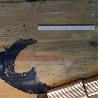
There is a fairly large difference in the ground level between the track side and the land side of the station. The prototype is sitting on heavy timbers and the ends were closed off with boards 6-7" wide. Take a close look Figure 2 to see what I mean. I used .100x.100 for the timbers and .030x.080 for the boards. Note that the ends of the boards on the east end appear to be broken off, so that’s the way I did mine. Figures 17-20 show the station at this point.
 |
| Figure 18. The nearly completed west end. |
 |
| Figure 19. Here you can see the roof details, the gutter, and the downspout. |
 |
| Figure 20. The land side of my model. Note the incredible wealth of detail on this side. Seriously, though, note that I added only the detail that could possibly be seen when the model is on the layout. |
The next step is to prime the model with a neutral gray. You can see from the photos that I’d done part of that before I added the roof. I was trying to get decent photos of the walls and the white plastic detail just didn’t show up against white plastic walls. After the primer is dry, spray the walls flat white. The trim along the bottom is light gray and the portion of the track side wall below the gray strip is black (I think the prototype has some sort of black preservative on it). Once the paint is dry, shingle the roof. My recent photos of the station show that it now has a metal roof. I'm not sure when the change was made, but a 1970 photo of the building clearly shows shingles. My favorite shingles are from Builders in Scale; whatever brand you use the shingles should be black.
 |
| Figure 21. The final detailing of the east end window is visible in this photo. |
I glazed the east end window with Micro Kristal Klear. When that has dried clear, cut a strip of .020x.040 to fit the width of the window inside the frame. I used a very small amount of ACC on each end to attach it even with the second horizontal crosspiece from the bottom. I don’t know why the board is there on the prototype, but it shows up in my pictures. It should also be painted white.
The next part was the hardest for me: the security bars over the east end window. They should be made of .012 wire. I made one attempt to use ACC to join the parts, but all I made was a big mess. So, I had to solder the darn things. There is a horizontal crosspiece halfway up the window and 6 vertical pieces spaced approximately evenly across the width of the window. With several hours of patient effort, a couple of burned fingers, and several bouts of uncontrolled swearing I got a reasonable approximation of the prototype. My version of the bars can be seen in Figure 21.
 |
| Figure 22. The final detailing of the west end is visible in this photo. |
The final detail is to add a Master Creations door knob to the door in the west end. A view of the finished west end can be seen in Figure 22. The station itself is now complete, except for the ramps to the freight doors. I’ll add those when I’ve completed the scenery in the station area. That won’t happen until I’ve finished the passenger station. Until then, the final shot (Figure 23) shows the station in place on the layout with a Gloor Craft Marlinton station standing in for the passenger station. I hope you’ve enjoyed this project; if so, drop me a line at the email address below.
 |
| Figure 23. The station in place on the layout. Compare this photo to Figure 2; I think I’ve done fairly well in capturing the Louisa station area. |
Stations |
|
You are visitor number
to this site since the new counter was inaugurated on June 28, 2004.
This site was originally established in 1997.
| Mail comments to: | Larry Z. Daily |
Please note that, due to a huge volume of spam coming in on my email account, I’ve had to change my email address. The new address is lzdaily@nospam.piedmontsub.com (but remove the nospam and the dot before piedmontsub.com).
Copyright © 1997-2025 Larry Z. Daily. All rights reserved.
All materials on this Web site are protected by United States
copyright law. This includes, but is not limited to, articles and graphics. Unless
otherwise indicated, these materials are the property of Larry Z. Daily and may not
be used without prior written permission of Larry Z. Daily