

 |
 |
 |
Modeling Campbell Depot
| [Menu] |
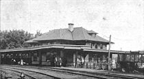
The inspiration for this project was a photograph I won in an eBay auction in 2011. As seen in Figure 1a, the photo was out of focus, faded, and had acquired a yellowish tint. I scanned it in and played with it a bit in PaintShopPro, with the results seen in Figure 1b. I usually resize photos I post to this site in order to save storage space, but I’ve posted the full-resolution scans here (click the thumbnails to get to them) in case someone else would like to work with them. If you do and you get better results than me (which probably won’t be hard to do), please share them. I’d love to see what you come up with.
I don’t know exactly when the photo was taken, but I have managed to narrow it down a bit. According to my sources, the Campbell depot was built in 1903. It was torn down in 1933. There is one other clue to the date, one that I’ve been able to glean from the photo. Above the waiting room door is a sign for the Adams Express Company. The C&O contracted with Adams until 1918. So, I’m pretty sure that the photo was taken between 1903 and 1918. Campbell station is an excellent example of the C&O’s standard station number 3, a design adopted by the railroad in 1892. The drawings called for a 10' by 15' waiting room at one end (the left side in the photo) and a 15' by 15' freight room at the other end, separated by an office with a bay window. The design is classic C&O. I was also drawn to the station sign, with the station number (which is roughly the mile post location of the station) above the station name, and the distance to Cincinnati on one side and (presumably) to Fort Monroe on the other.
In the summer of 2013 I went to the C&O Historical Society convention in Pipestem State Park in West Virginia. While browsing the sale tables, I saw a kit for a C&O standard station number 3. I managed to ignore it for a couple of days, but eventually its siren song wore me down. I went to the table, pulled up my photo of the Campbell station on my Smart phone, and when I saw how close the match seemed to be, I bought myself a kit. My plan was to build the kit to match how the station looked in the photo, most likely as part of a diorama.
I hadn’t really thought about what color the station was until I got the kit home and really started looking at the photo of Campbell depot. I usually model 1970 and, at that time, stations — if they got painted at all — just got a coat of white over everything. The C&O is probably best known for its three-tone gray paint scheme for stations and I just assumed that I’d paint the station in that scheme. As I dug into C&O painting standards, however, I ran into problems. Beginning in 1898, the C&O began painting stations cadmium yellow (which can look a bit orange) with white trim and maroon doors and window sashes (see this photo of the restored Alderson station for an example). In 1905, they adopted a scheme that used colonial buff (a light yellow) for the walls with white trim and terra cotta doors and sashes (see the restored Marlinton station for an example). The well known gray scheme was adopted in 1924. If the photo shows the station sometime between 1903 and 1918, it is most certainly not gray.
The question is, what color is it? The above information suggests that it was painted in the cadmium yellow scheme when built and could have been repainted into the colonial buff scheme sometime between 1905 and 1918. But, look closely at the photo. To almost every one who looks at it, the trim looks darker than the walls (my son says the trim looks the same color as the walls to him). So, what’s the problem? In both of the possible paint schemes, the trim was white and should look significantly lighter than the walls! The best guess that I have (first suggested by Karen Parker) is that the shop forces ignored the standards and painted the walls cadmium yellow and the trim and everything else maroon, leaving off the white. For what it’s worth, after I began construction of the model I discovered another station that apparently ended up with light walls and dark trim: Marlinton! There’s a photo of Marlinton on page 16 of the book Chesapeake and Ohio Standard Structures that clearly shows light walls and dark trim. A search of the C&O Historical Society Archives also turned up a photo of the station in that scheme ( COHS 35237). The caption says that photo is from 1910.
I recently had a friend who specializes in photography in my university’s Art department take a look at this photo to see if he could tell me anything about the color. Rick Bruner spent a good amount of his time talking to me about the photo and color. His conclusion: the walls are light and the trim is about 10% darker. When I described the two options to him — orange with maroon or light yellow with terra cotta — he went with the yellow (colonial buff) walls with terra cotta trim.
Following a suggestion in the archive of the ChesapeakeOhioRailway Yahoo group, I bought the paints for the Colonial buff scheme: FolkArt number 432 Sunflower for the Colonial buff and Polly Scale F414293 Zinc Oxide Primer for the terra cotta. I painted a sample wall section, photographed it, and then started playing with the photo. My first step was to convert it to a black and white photo, then mess it up in any way I could to try and match the prototype photo. The results were that I couldn’t ever get it to look like the photo. The contrast between the buff and the terra cotta was just too great. Then it occurred to me to try my test on a prototype photo. I used the one of the Marlinton station that I linked to above. I ended up with the same results: the contrast between the buff and the terra cotta was always too much.
The kit was produced some years ago by State Tool & Die and includes laser cut wood for the walls and the decorative verge boards at the gables and stripwood for the trim. My first impression on opening the box was a good one. As I compared the kit to the prototype, however, I noticed a bunch of differences (some of them are called out in Figure 2). As I got deeper into the planning process, more and more differences between the kit, the official C&O drawings, and the prototype Campbell depot emerged. Here’s a partial list (roughly in the order in which I discovered them):
As I said, this list grew as I was putting it together. It started with only 5 bullets, most minor. It now lists 9 discrepancies, some of them major. That left me, as I saw it, with three options.
As I thought about this project more, I realised that somewhere in the planning I got a bit invested in the idea of modeling Campbell depot. I like the station and I’m intrigued by how it will look done up in cadmium yellow and maroon. Besides, I’ve always wanted to model one of the C&O’s American-style steam locomotives. Having a diorama of a station from the turn of the century (19th to 20th) would give me a place to display that model. Is it clear at this point that I can rationalize with the best of them? So, here’s how I built the station:
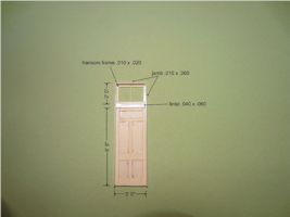 |
I had a bunch of parts left over from a couple of Gloor Craft’s Marlinton depot kits that I used when I built my model of the Louisa station. I first looked at the doors to see if I could use those. As it turned out, they didn’t quite match the doors on the station at Campbell, so I resolved to build my own. Here’s my model of the waiting room door. The main part of the door was cut from .020 styrene sheet. The stiles and rails were made from strips cut from .005 sheet styrene. Other dimensions are called out on the drawing. |
 |
None of the Marlinton kit freight doors matched either. Here’s my model of the freight room door. The biggest issue here was working out the dimensions. I ended up printing the photo out as close to HO scale as I could get it and measuring straight from that. There are still some slight issues with skew (the photo wasn’t taken quite at 90 degrees to the station wall), but I think it’s close. Each door is 3' 3" wide and 6' 9" tall. Many of the framing members are the same size as the waiting room door. The transom windows are 1' 6" tall. |
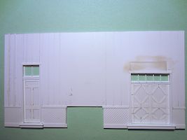 |
Here’s the front (trackside) wall with the doors installed. The top part of the wall was cut from .020 styrene sheet. The wainscotting was made from some Evergreen siding that I had left over from building the Louisa station. The trim is made from scale 1x4 styrene. You’ll note that I made one giant error on the front wall. After noting that the prototype freight room door didn’t match the drawing, I cut the opening to match the door in the drawing. I’ve filled the unneeded part of the opening with a patch cut from .020 styrene. I still need to work on hiding the gap a bit better. Fortunately, the station sign will help hide the error. Before you start cutting styrene, though, you might want to see below. |
 |
In this shot I’ve completed the front wall by adding the bay window and the battens. The battens are scale 1x3. The wainscotting and the top part of the bay area are made from the same Evergreen siding as the wainscotting on the wall. The framing around the windows is made from .020x.060 styrene strip. The windows themselves were cut made from .005 styrene strips which were very graciously given to me by Bob Hundman years ago. I deliberately left the corner posts (which are made from scale 4x4’s) a bit long so that I can cut them to match the angle of the end walls once those are added. |
 |
Here’s the end wall from the waiting room end of the station. Note that I used a leftover window from the Marlinton station kit. |
 |
This is the freight room end wall. Note that I haven’t yet trimmed all of the battens. |
 |
I’ve glued the end walls to the front wall. I reinforced the corner joints from inside with .100 x .100 styrene strip. I also ran a length of the .100 x .100 strip about 1⁄8" below the top of the front wall to prevent warping. |
 |
Here’s the back wall. The freight room door was built to the same dimensions as the freight room door in the front wall. The windows are from the Marlinton station kit. |
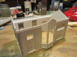 |
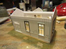
I now have all four walls together. In looking at the model, I think I’m going to have to add interior walls. I don’t plan to detail or light the interior, but that big bay window allows too much of the interior to be seen. So, I’ll add the two interior walls and, perhaps, the work table located in the bay. |
 |
|
 |
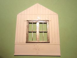
Here are the new front and waiting room end walls. That’s right, the new walls. While I was waiting for Rick to get back to me on the color issue (see above), I began studying my scans of the photo even more intensely and found a few things that I had overlooked. First, on the prototype the wainscotting on the bay clearly doesn’t come up as far as the wainscotting on the wall, but I built them the same height. I had also followed the drawings (silly me) when I built the doors, in the sense that I had the top of the threshold even with the top of the trim strip at the bottom of the wall. As I began to explore placing the station on the platform, it was clear that the thresholds would be 6 scale inches over the platform. That was not good. There were a few other things I found, so I decided to start over. The wainscotting is 4' in height and all the trim is scale 1x6. |
 |
|
 |
Here’s the interior wall between the waiting room and the operator’s office. I’m using photos that I took inside the Louisa station to guide its construction. I really don’t intend to fully detail the interior, but with the big windows in the end wall and the bay window in the office, it would be really apparent if there were nothing inside. Then again, it did occur to me that I could light the interior with a couple of LED’s powered by a battery under the diorama and if I light the interior there would have to be stuff in there to look at, right? |
 |
I’ve added the interior walls to the model now. The next step is to begin painting the model. According to a post by Todd Hanger on the the ChesapeakeOhioRailway Yahoo group, the interior should be silver gray and terra cotta. At least, that’s how they painted the interior of Alderson during the renovation. In the absence of any other info, that’s what I plan to go with, even though the guys who built Campbell depot seemed not to follow the standards any too strictly. |
 |
So, if you look at this photo, I seem to be back to where I was a few weeks ago. That’s not strictly true, though.The last time I had all four walls together I didn’t have the interior walls in. I also hadn’t painted the model. If you look closely, you can see that the model is no longer white. It’s a very light silver gray. I mixed up a color for the interior walls that looked right to me (a one-to-one mix of Polly Scale Undercoat Light Gray and Reefer White). Then I decided that it would make a great primer. So I sprayed the whole thing with it. |
 |
I decided to spend some time on the floor while the primer coat dried. I cut it from O scale car siding. The next step was to get a polished wood look. I spent some time in the summer of 2013 building a couple of Sopwith Camel models (see Sopwith Camel Models). World War I planes often had polished wood surfaces, so I learned a technique to duplicate that and I thought that technique would work here. First, I put down a base coat of Model Masters Sand. I let that dry for several days. |
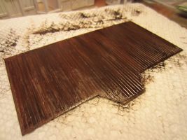 |
The next step involves a wide, soft brush and artist oil colors. I used burnt umber. I slathered on a decent coat, wiped the paint off the brush, and kept going over the surface — brushing with the direction of the desired grain and then wiping excess paint from the brush — until I got the stained wood grain effect that I wanted. Then I set it aside; it takes the oil paint a good long time to dry. When it’s dry I’ll give it a coat of semigloss clear to protect it. |
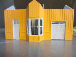 |
The primer was dry by this point, so I went back to painting the walls. In this shot, I’ve got the cadmium yellow on. The next step is to paint the maroon trim and doors. |
 |
Here’s the front wall with the doors and trim painted. I decided go with Polly Scale Special Oxide Red for the maroon. It was the best match that I had to the color I saw in the photos I took of Alderson. |
 |
I’ve added the floor and some rudimentary interior detailing. I’ve decided not to light the interior, but enough light gets in through the windows to require something inside. I painted the walls with the silver gray mix mentioned above with Polly Scale F414293 Zinc Oxide Primer for the terra cotta. In terms of detail, I added a pair of stoves, a table in the bay, and a bench in the waiting room. |
 |
|
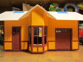 |
Well, it’s time for the roof. The shape of the main roof panels was easy to determine. They were cut from .020 styrene sheet. The roof panels over the bay were a bit more difficult. I cut test pieces out of old business cards. These look about right, so I’ll use them as patterns to cut pieces from styrene. Then I just need to glaze the windows (I plan to use .010 clear styrene sheet) and then I can add the roof. |
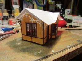 |
In this shot, the roof pieces have been attached and I’ve added the roof braces and the decorative vergeboards at the end gables. I’ve used the metal trim pieces from the old Gloor Craft Marlinton Statio kit. |
 |
The fascia was constructed of two layers of styrene strip. The back layer is scale 1x8 and the front is scale 1x4. |
 |
I’ve started construction of the gable trim for the bay. The Gloor Craft piece didn’t fit this smaller station. I’m cutting the pieces to size over a copy of the prototype that I printed out sized to match HO scale. The wide pieces are scale 4x12 (ok, I laminated scale 1x12 that I had on hand to get the right thickness). Most of the other pieces are made of 2 layers of scale 2x4 to match the prototype’s 4x4 lumber. I used the layers of 2x4 to avoid having to try and cut very exact notches where the timbers crossed one another. |
 |
The gable trim for the bay is completed and installed. The hard part with finishing up the trim was finding something to represent the balls on the ends of the timbers. I finally found the answer — not at the hobby shop, the craft store, or some online modeling venue — but at the grocery store. The balls are the little candy sprinkles used on cakes and cookies. In this shot, the trim has all been painted. Next up: shingling the roof. |
 |
The shingles I’m using are from Builders in Scale. I had several packages of them on hand, so it seemed a logical choice. |
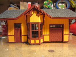 |
About halfway up the roof I realized that I needed to add the chimney. You can see it in this shot. I build it out of several layers of styrene with a brick sheet overlay. It still needs painting. The next step is to build the platform. |
 |
Ok, so I was wrong. The next step was to add the roof flashing. I made it from .005 styrene sheet cut into strips a scale 6 inches wide and some Builders in Scale metal roofing. |
 |
The intent was to represent copper flashing. To replicate weathered copper I started by painting the flashing with several coats of PollyScale Roof Brown. I let the paint dry thoroughly between coats and before going on to the next step. |
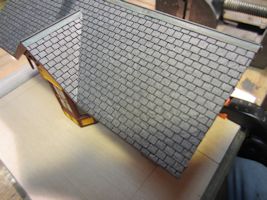 |
Next, I made a fairly strong wash using distilled water and PollyScale Penn Central green. I applied the wash liberally to the flashing.This photo shows the flashing after the wash dried. I think it looks like weathered copper. Next up: building the platorm (I mean it this time) and adding signs to the station. |
 |
Ok, now I’m starting the platform. I decided that I didn't want to build up the platform supports board by board, so I opted for a core of 1/8 inch basswood. I took the dimensions of the platform from the drawings, then subtracted a scale 4 inches from the length and width. That allowed me to add scale 2x10 lumber to the edges. In this photo I’ve started adding the platform surface, which is made of scale 2x12 lumber. All of the boards were cut to size and then stained with Micro-Mark’s Gray/Brown stain. |
Menu |
You are visitor number
to this site since the new counter was inaugurated on June 28, 2004.
This site was originally established in 1997.
| Mail comments to: | Larry Z. Daily |
Please note that, due to a huge volume of spam coming in on my email account, I’ve had to change my email address. The new address is lzdaily@nospam.piedmontsub.com (but remove the nospam and the dot before piedmontsub.com).
Copyright © 1997-2024 Larry Z. Daily. All rights reserved.
All materials on this Web site are protected by United States
copyright law. This includes, but is not limited to, articles and graphics. Unless
otherwise indicated, these materials are the property of Larry Z. Daily and may not
be used without prior written permission of Larry Z. Daily
| The author strongly supports | Site edited with | Photos edited with | Maps created with | Tooltips created with BoxOver | The site counter is a product of |
|
|
|
|
|
|
|